MZ-RH1 Display Module Installation Guide
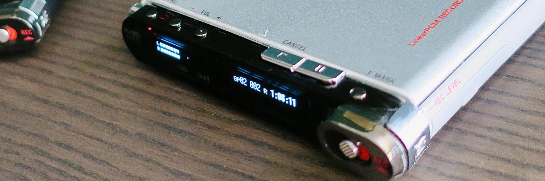 Photo credit: SirDreamWorks
Introduction
This guide offers step-by-step instructions for installing our replacement display in the Sony MZ-RH1 MiniDisc player. Use this guide as a helpful reference to restore your device’s functionality with the new display module.
Before you begin the installation, please carefully read through this guide and gather all necessary tools and materials. It is also crucial to follow all handling precautions, as the replacement displays are built with flexible PCBs and are sensitive to electrostatic discharge (ESD). Taking these precautions will help ensure a successful installation.
With a little patience and attention to detail, you will have your MZ-RH1 back in top working condition in no time. Let’s get started!
We also welcome any contributions to improve this guide. If you have suggestions or better-quality photos that could enhance the instructions, feel free to share them with us!
Handling Precautions
⚠️When installing the replacement displays, please handle the modules with great care. The modules are built using flexible PCBs, which can be delicate and prone to damage if not treated carefully.
Additionally, the display modules and MZ-RH1 PCBs are sensitive to electrostatic discharge (ESD). To prevent any potential damage, we recommend to take appropriate ESD precautions, such as:
-
Use an Anti-Static Wrist Strap: Wear an anti-static wrist strap connected to a grounded surface to safely dissipate any static electricity that may accumulate on your body.
-
Work on an ESD-Safe Mat: Ensure your workspace is equipped with an ESD-safe mat to provide a controlled environment that prevents the build-up of static charge.
-
Avoid Touching Conductive Parts: Whenever possible, avoid touching the conductive parts of the module. Handle the display by the edges to minimize the risk of static discharge or physical damage.
By following these precautions, you will help ensure a successful installation and prolong the life of your replacement display.
Disclaimer
While we have made every effort to ensure the accuracy and comprehensiveness of this installation guide, we cannot be held responsible for any damage that may occur to your MZ-RH1 or any other equipment during the installation process. This includes, but is not limited to, damage resulting from improper handling, failure to follow the instructions, or any unforeseen issues that arise during the replacement of the display. By proceeding with the installation, you acknowledge and accept that you are doing so at your own risk. We strongly recommend that only those who are comfortable working with electronic components and have experience with similar repairs attempt this installation. If you are unsure about any part of the process, please seek professional assistance.
Getting Started
Recommended Video Guide
For those looking for a visual walkthrough of the installation process, we highly recommend watching the instructional video created by Technical Initiative. While the video demonstrates how to install revision E of the replacement module, it also applies to newer revisions such as Rev-F. In general, it provides a helpful overview of the steps involved in opening the MZ-RH1 and replacing the display. Watching the video can give you a clearer understanding of the process and help you feel more confident as you proceed with the installation.
Opening up your MZ-RH1
1: Remove Battery and Disk
Before starting disassembly, remove both the battery and any MiniDisc inside the device.

2: Remove Outer Screws
Start by removing the 4 exterior screws located on the bottom and back of the device. Then remove the battery door and the hidden screw underneath it. Gently pop out the rear cover.


3: Remove Inner Screw
Unscrew the single middle screw that secures the front display unit.


4: Remove Display Unit
Carefully dislodge the ribbon cable by wiggling it gently. Then, remove the front display unit, which is hinged on the MD drive side.


5: Open Display Unit
Remove the 3 screws holding down the silver back plastic on the display unit. One is in the middle, one on the right, and the last one on the far right. Removing the far-right screw also loosens a small metal bracket that holds the silver back plastic.

Once removed, the display and control PCB are exposed:

6: Remove Display PCB
Unscrew the screw located on the far left at the bottom of the PCB — this is the only screw holding the PCB in place.

Carefully lift the PCB to expose the OLED display connectors underneath. Move the jog dial down to create clearance for removing the PCB, which can only be removed one way.

7: Disconnect and Remove OLEDs
To disconnect the OLED displays, carefully lift the clip to unlock the ZIF connectors securing the ribbon cables.

Refer to the photos below for locked and unlocked ZIF connectors:


Once disconnected, remove the two screws, the rubber piece, and the “T-Mark” button. The left screw secures the jog lever spring, while the right screw holds the display carrier bracket to the outer plastic shell.


When the screws are removed, carefully lift out the display carrier board.


Installing the New Module
8: Remove OLEDs from Internal Carrier Bracket
Start by removing the plastic film glued to the OLED displays. Using isopropyl alcohol or a low-heat hairdryer can make this easier. The film prevents OLED bleeding and can be reused with the new displays if you wish.
⚠️ Avoid overheating the plastic, as it can melt. If you’re unsure, it’s safer to skip the heat and use isopropyl alcohol instead. ⚠️

Next, remove the OLEDs from the plastic bracket. Use a heat gun or hairdryer to loosen the glue, and carefully pry the displays out using an old credit card.


Once the old OLEDs are removed, clean the surface with isopropyl alcohol to remove any glue residue.

9: Modify the Internal Bracket (Skip this for Rev-F+)
To fit the new module, you’ll need to modify the bracket by trimming away part of the center plastic piece. Use the following photos as a guide:


Ensure there are no sharp edges and that the final surface is flat.

10: Test the New Display Module
Before final installation, test the new OLED displays. Connect them to the ribbon connectors and attach the PCB to the main board via the single ribbon. Ensure that the ribbon cables are properly oriented, and verify the display works.


⚠️ Ensure the display ribbon cables are properly seated in the ZIF connectors. Poor connections can damage the displays! ⚠️

11: Install the New Display Module
Place the new display module into the bracket as shown below:

You can use some (thin) double sided tape to help with the installation. From Revision E* the units have pre-applied double-sided tape, so you do not need to source your own.
⚠️ Be careful not to place tape over the conductive copper pads (bottom-left corner on Rev-E), as it could cause shorts. ⚠️

Remove the protective covers from the new displays before final installation. Optional: At this point you may want to reinstall the black foil that covered the original OLEDs, as this will prevent light bleeding through the edges of the new OLEDs. If you do, retest the display to make sure that you haven’t accidentally covered part of the visible area.

12: Reinstall the Carrier Bracket
Reinstall the carrier bracket by placing the 3-button plastic piece into the outer shell. You can tape it from the outside to hold it in place temporarily, making the installation easier. Carefully place the bracket back in, as shown:

Closing your RH1
13: Reinstall Spring and Buttons
Reinstall the jog wheel spring, screws, and T-Mark button:


14: Connect the Displays and Reinstall PCB
Connect the displays and carefully fold the ribbon cables as shown in the photos before reinstalling the PCB. When installing the PCB, make sure that the jog lever spring is properly aligned!
⚠️ Sony’s display PCB is thin and flexible. Do not put too much pressure on the middle of the PCB during re-installation, as that can cause it to bend and poke the connectors on the backside into the new display module, potentially damaging it. ⚠️

Ensure the ribbons fold correctly:


15: Securing the Display PCB and Connect the FPC Cable
Reinstall the screw securing the PCB and attach the FPC cable.
⚠️ Be gentle with the buttons on the PCB — they are delicate and may break if forced! ⚠️


16: Closing the Display Unit
Reassemble the display unit by reinstalling the silver plastic.
Remember, the metal piece on the right side must be installed last, as it hooks over the silver plastic:
17: Closing the RH1
Follow the earlier steps in reverse to reinstall the front display panel and fully reassemble your MZ-RH1.
18: The End!
Congratulations! You’ve successfully completed the installation of your new OLED display module for the Sony MZ-RH1. With these new displays, your device should be fully restored and ready for many more years of use. We hope this guide has provided clear and helpful instructions throughout the process.
As always, handle your device with care, and if you encounter any issues or have additional questions, feel free to reach out. Thank you for supporting this project, and enjoy your rejuvenated MZ-RH1!
Credits
- Project Development: Sir68k
- Video Tutorial: Technical Initiative (YouTube)
- Photo Contributions: Many thanks to SirDreamWorks, HexaPunk, Baz, and Kish for supplying photos to improve this guide.
- Text Contributions: Some sections are based on Kish’s installation guide for the early prototype units.
- Legacy Sales Partners: Gunner5 for North America
A special thanks to the MiniDisc community for their continued support and valuable feedback throughout this project!